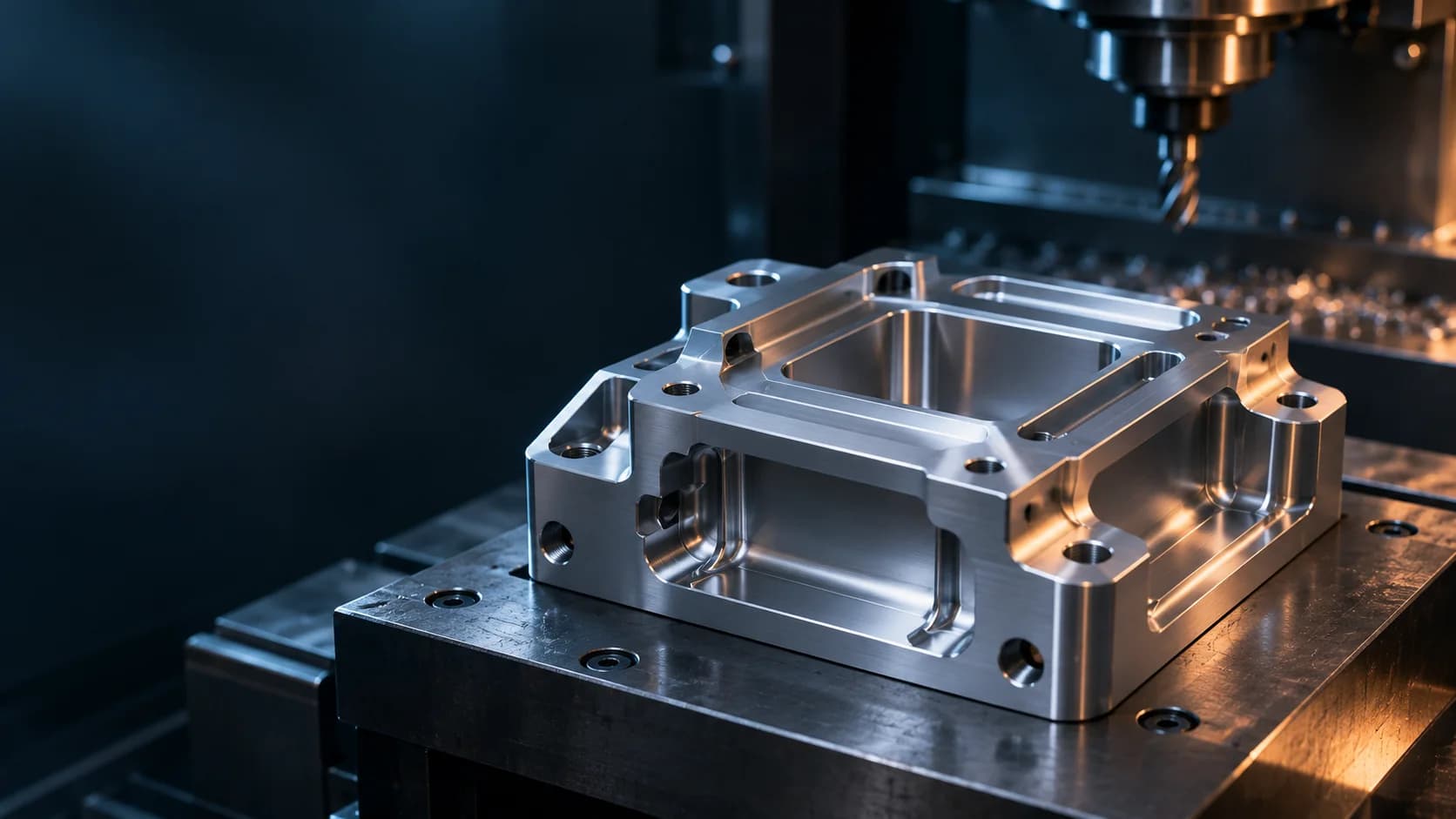
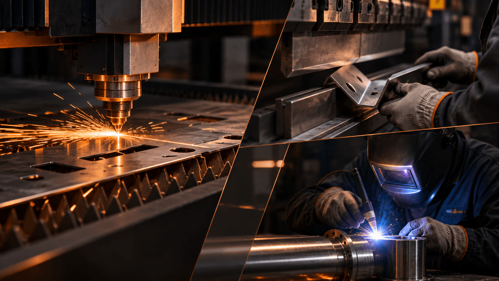
From 3-, 4- and 5-axis machining to CNC turning and specialist manufacturing routes, we connect the operations needed to deliver your finished component.
Select a machining route to explore its role in part production. Geometry, material, quantity and machine availability determine the final route.
SELECT A PROCESS01 — 04
TECHNICAL ROUTE / DEFINED BY PROJECT
PROCESS VIEW / 01X / Y / Z
X / Y / Z MOVEMENT
Precision in three directions.
An efficient starting point for planar features, pockets, holes and detailed prismatic components. The route is planned around setup, workholding and the features that need to be accessed.
Prismatic components
Production-ready milling routes
Tooling and setup planning
CAPABILITY / FEASIBILITY-LED01 / 04
01A / MANUFACTURING INFRASTRUCTURE
Built for precision. Equipped for production.
Our manufacturing infrastructure brings together precision machining, specialised production equipment, high-pressure die casting, component finishing and dimensional inspection. We review the right route for each drawing, material and production requirement.
12VMC machines
22SPM drilling & tapping machines
2Die casting machines
1CMM inspection machine
01 / EQUIPMENT
Precision machining & production
A machine base supporting milling, turning, grinding and repeat drilling and tapping operations.
Vertical Machining Centres (VMCs)12
Turning machine1
M1TR turret milling machines2
Surface grinding machine1
Cylindrical grinding machine1
SPM drilling & tapping machines22
02 / EQUIPMENT
High-pressure die casting
Two machines for suitable die-cast components, subject to part geometry, tooling and production feasibility.
150-ton high-pressure die casting machine1
250-ton high-pressure die casting machine1
03 / EQUIPMENT
Component finishing & thermal equipment
Supporting equipment for project-specific component tumbling, baking and furnace operations.
Component tumbling machine1
Industrial baking ovens2
Industrial furnace1
04 / EQUIPMENT
Inspection & production tooling
Dimensional verification and project-appropriate tooling to support controlled manufacturing.
Coordinate Measuring Machine (CMM)1
Production tooling, fixtures & workholdingAvailable
02 / BEYOND THE CUT
More than one way to manufacture.
Machining is one part of a broader manufacturing picture. The best starting route depends on what the component actually needs.
01 / NEAR-NET-SHAPE↗
CAST / FORM
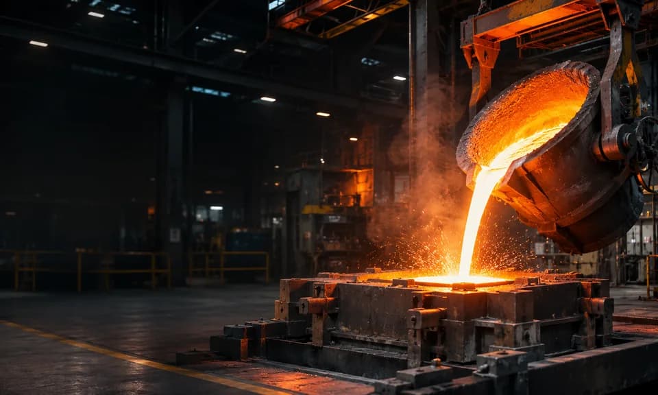
Casting
Explore casting routes where component geometry, quantity and material make a formed starting shape the right choice.
02 / FORMED STOCK↗
FORGE / SHAPE
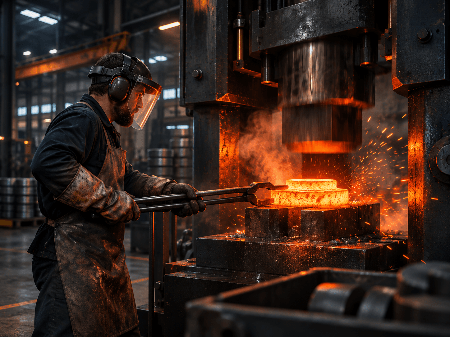
Forging
Review forging as a manufacturing route where material characteristics and the intended application call for it.
03 / MIM↗
MIM / DETAIL
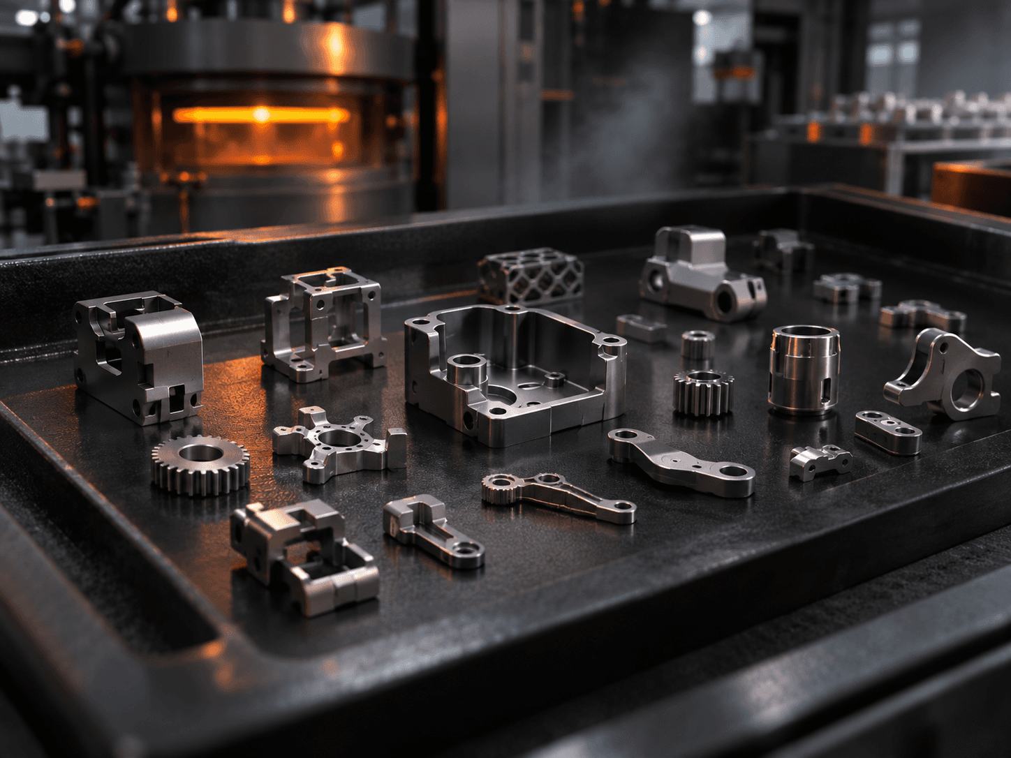
Metal Injection Molding
Consider MIM for suitable small, complex metallic components and production requirements, subject to feasibility review.
04 / PROJECT-SPECIFIC↗
REVIEW / ROUTE
Other manufacturing routes
When a component needs a different process, we review viable methods and define the manufacturing and supplier scope.
Manufacturing methods may be performed or coordinated through approved specialist partners; the proposed route and responsibility are confirmed for each project.
02A / INTEGRATED MANUFACTURING
ONE MANUFACTURING ROUTE. DEFINED RESPONSIBILITY.
From the starting form. To the final feature.
Our manufacturing approach connects suitable casting, forging and MIM routes with CNC finishing, surface treatment and inspection, so OEM teams can review the complete supply scope in one conversation.
Investment casting, forging or metal injection molding (MIM) can be assessed where geometry, material and volume justify a formed starting component.
02 / MACHINE↗
Precision CNC finishing
3-, 4- and 5-axis machining and CNC turning support the features, interfaces and dimensional requirements defined by the drawing.
03 / FINISH↗
Surface treatment
Anodizing, deposited coatings and other treatments are reviewed for material compatibility, specification and production route.
04 / VERIFY↗
Inspection & handover
Inspection scope, traceability, documentation, packaging and delivery are agreed as part of the manufacturing programme.
Process availability, in-house versus specialist-partner responsibilities, capacity and inspection coverage are established during technical and commercial review.
02B / TECHNICAL DATA PACKAGE REVIEW
Engineering standards. Defined by your drawing.
Technical requirements are reviewed against the customer-specified edition of each applicable standard. The examples below guide early manufacturing discussions; they are not a declaration of certification or blanket process approval.
CATEGORYREFERENCE / REQUIREMENTWHAT WE REVIEW
01 /Drawing & GD&T
ASME Y14.5 · customer drawing revisions
Datums, feature control frames, inspection characteristics and acceptance criteria reviewed against the supplied technical drawing.
02 /General tolerances
ISO 2768 where specified · drawing-specific requirements
Applicable standard editions, material conditions and tolerance classes confirmed for each project; no default tolerance class is assumed.
03 /Aluminium finishing
MIL-PRF-8625 · anodizing requirements
Type, class, colour, thickness, material compatibility and inspection requirements reviewed with the coating route.
04 /Steel surface treatment
MIL-DTL-16232 · phosphate / conversion coatings
Customer-specified treatment, corrosion protection and acceptance checks assessed for process availability and scope.
05 /Quality evidence
CMM reports · FAI · PPAP · SPC · material traceability
Deliverables, sampling plans and any process-capability targets defined in the purchase order or approved quality plan.
SPECIFICATION → PROCESS REVIEW → INSPECTION PLAN → AGREED EVIDENCEExplore our approach ↗
03 / MATERIAL-LED PLANNING
Material first. Process next.
Ferrous and non-ferrous requirements are reviewed with the end-use in mind—not chosen from a generic list.
We consider surface treatment as part of the manufacturing plan, aligning the finish with the substrate, specification and intended application.
SECTION STUDY / SURFACE LAYERS
SURFACE LAYERBASE MATERIAL
01
PVD
Physical vapour deposition
↗
02
CVD
Chemical vapour deposition
↗
03
Powder coating
Protective and decorative finishes
↗
04
Ceramic coatings
Specialist coating systems
↗
05
Anodizing
For compatible substrates
↗
06
Specialty coatings
Reviewed against your specification
↗
Coating availability, third-party processing, substrate compatibility, specification and acceptance criteria are subject to project review. “Ceramic coatings” includes suitable systems as agreed for the application.
05 / THE FINAL HANDOVER
Manufactured here. Prepared to arrive.
Custom packaging is available for products manufactured by Dynamack Components. The protection, identification and delivery format are defined around the part and the agreed order requirements.
Each project is planned around an agreed scope, with operations, inspection and handover linked rather than treated as disconnected activities.
01 ↗
Define
Application, drawing, material and acceptance criteria
02 ↗
Plan
Process route, tooling, supply and inspection
03 ↗
Produce
Machining and agreed secondary manufacturing
04 ↗
Complete
Finishing, inspection, records and packaging
YOUR NEXT COMPONENT / OUR NEXT CONVERSATION
Bring the requirement. We’ll map the route.
Tell us the material, approximate quantity, drawing status and intended application. We’ll review process fit, manufacturing scope and the next step. Restricted drawings should only be shared through an agreed secure channel.